Color Code Resistor Calculator
Valor de la resistencia: 0 Ω
To create this calculator, the IEC 60062:2016-07 standard of the International Electrotechnical Commission (IEC) was followed. This document replaces the one published in 2004, incorporating some significant changes compared to the previous edition. One of these changes is the introduction of a pink color for the 1 mΩ multiplier coding. Another significant point is that the tolerance band is marked by increasing its width to 1.5 to 2 times the width of the other bands. It should be noted that another widely used method to mark the tolerance band is by increasing the distance between the multiplier band and the tolerance band. However, considering the small differences that exist between this standard and previous ones, the method for obtaining resistance values essentially remains unchanged.
General Rules
The color code is applied using a sequence of solid color bands, where the first band is placed closer to one end of the resistor. These bands are organized and spaced in such a way as to avoid any confusion when reading the coding. The band indicating tolerance is wider, with a thickness between 1.5 and 2 times that of the other bands, to ensure clarity. Any additional coding is designed so that it does not interfere with the interpretation of the value and tolerance. Although ideally the color bands should form complete rings around the cylindrical body of the resistor, incidental interruption of the band is permitted as long as at least two-thirds of it are visible from any radial viewing angle.
Calculation of Resistance Values with Color Code
Resistors can be marked with electrical resistance values, temperature coefficient, and precision or tolerance. In the case of axial packaging, color stripe codes are used to label these values. There can be three, four, five, or six stripes as shown in the following image.
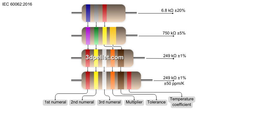
When resistors are marked with two significant figures, they can have three or four bands. The first two bands correspond to the values of the two significant figures, and the third represents the multiplier value. These three values together give the resistance value in ohms. The fourth band is wider and represents the tolerance. The absence of the fourth band indicates a tolerance of ±20%.
Resistors with resistance values described by three significant figures can be marked with a five- or six-band color code. The first three bands are for the significant figures, followed by a band for the multiplier, a wider band for the tolerance, and finally, a band representing the temperature coefficient of the resistor. In other words, the band representing the temperature coefficient of the resistor (the sixth band) is only used in combination with a three-figure resistance code and is in addition to the five-band marking for resistance value and tolerance.
Resistor Color Code Chart
The colors black, brown, red, orange, yellow, green, blue, violet, gray, and white are used to represent the numbers 0 to 9 for each significant figure. Additionally, with the inclusion of the colors silver, gold, and pink, they are used to indicate the multiplier, tolerance, and temperature coefficient of resistance. The following table details the colors along with their assigned parameters and corresponding values.
| Color | Digit | Multiplier | Tolerance | TC |
|---|---|---|---|---|
None |
- | - | ±20% | - |
Pink |
- | 10^-3 (1 mΩ) | - | - |
Silver |
- | 10^-2 (0.01 Ω) | ±10% | - |
Gold |
- | 10^-1 (0.1 Ω) | ±5% | - |
Black |
0 | 10^0 (1 Ω) | - | ±250 ppm/K |
Brown |
1 | 10^1 (10 Ω) | ±1% | ±100 ppm/K |
Red |
2 | 10^2 (100 Ω) | ±2% | ±50 ppm/K |
Orange |
3 | 10^3 (1 kΩ) | ±0.05% | ±15 ppm/K |
Yellow |
4 | 10^4 (10 kΩ) | ±0.02% | ±25 ppm/K |
Green |
5 | 10^5 (100 kΩ) | ±0.5% | ±20 ppm/K |
Blue |
6 | 10^6 (1 MΩ) | ±0.25% | ±10 ppm/K |
Violet |
7 | 10^7 (10 MΩ) | ±0.1% | ±5 ppm/K |
Gray |
8 | 10^8 (100 MΩ) | ±0.01% | ±1 ppm/K |
White |
9 | 10^9 (1 GΩ) | - | - |