How to Control a Servo Motor Using Arduino
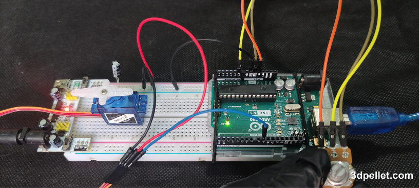
Servo motors are widely used in electronics and robotics projects due to their precision and ease of control over angular position. In this article, you will learn how to control a servo motor using an Arduino.
Required Hardware
To follow this tutorial, you will need the following components:
- Arduino board
- Servo motor
- Potentiometer
- 5V power supply
- A 100 µF capacitor
- Breadboard
What is a Servo Motor?
A servo motor is an electromechanical device that converts an electrical signal into controlled motion. It is a direct current (DC) motor with a control system that allows the shaft position to be maintained at a specific angle. Servo motors can maintain a fixed position thanks to a feedback loop that measures the current shaft position and adjusts the power supplied to the motor to correct any deviation from the desired position.
Servo motors have different power requirements depending on their size and the workload they experience. A common and widely used servo motor for educational purposes is the micro servo SG90. This motor can be powered directly with an Arduino, but it is highly recommended to use an external power source to maintain the same circuit whether you want to increase the number of servos to handle or use a larger servo.
Servo motors are popular in applications that require precise position control, such as robots, remote-controlled airplanes, and automated mechanisms.
Main Components of a Servo Motor
A servo motor has four fundamental elements:
- DC Motor: Provides the movement.
- Gearbox: Reduces speed and increases torque.
- Potentiometer: Provides feedback on the angular position of the shaft.
- Control Circuit: Receives the control signal and adjusts the DC motor position.
Input Distribution
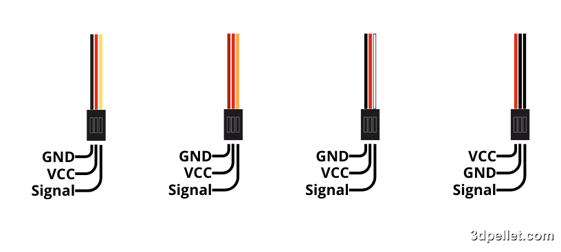
A servo motor has three wires:
- Signal: Pulse-width modulation (PWM) signal to control the servo.
- Vcc: Positive power supply.
- GND: Ground.
The typical colors of these wires are usually orange or yellow for the control input, red for Vcc, and brown or black for ground. These combinations are shown in the following figure.
Control Signal
The control signal of a servo motor is a PWM signal. This signal consists of a series of pulses that indicate the desired position of the servo motor’s shaft.
PWM Signal Characteristics
-
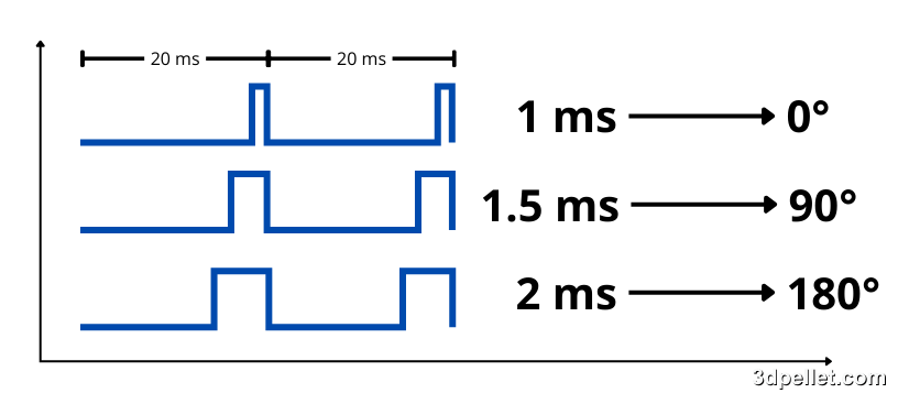
Frequency: Typically, the frequency of the PWM signal is 50 Hz (20 ms period).
-
Pulse Width: The pulse width typically varies between 1 ms and 2 ms.
- A 1 ms pulse positions the servo motor at its minimum angle (0 degrees).
- A 1.5 ms pulse positions the servo motor at its central position (90 degrees).
- A 2 ms pulse positions the servo motor at its maximum angle (180 degrees).
The pulse width determines the angular position of the servo motor’s shaft. For example, if the pulse width is 1.5 ms, the servo motor will position itself at 90 degrees.
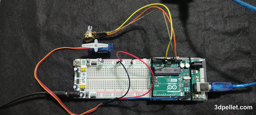
Hardware Connections
To control the servo with an Arduino, a system will be used that bases its control on the operation of a potentiometer, which serves to indicate to the microcontroller, through the signal read by one of the analog pins, the angle at which the servo should rotate. A 5V power supply will be used to power the servo. If your project requires mobility without relying on a power outlet, you can use batteries to power the servo. To obtain exactly 5V, you can use two 18650 lithium-ion batteries combined with a buck converter.
The simplest way to reduce a direct current voltage is to use a voltage divider circuit, but dividers waste a lot of energy as heat. Therefore, it is advisable to use a buck converter since these have high efficiency.
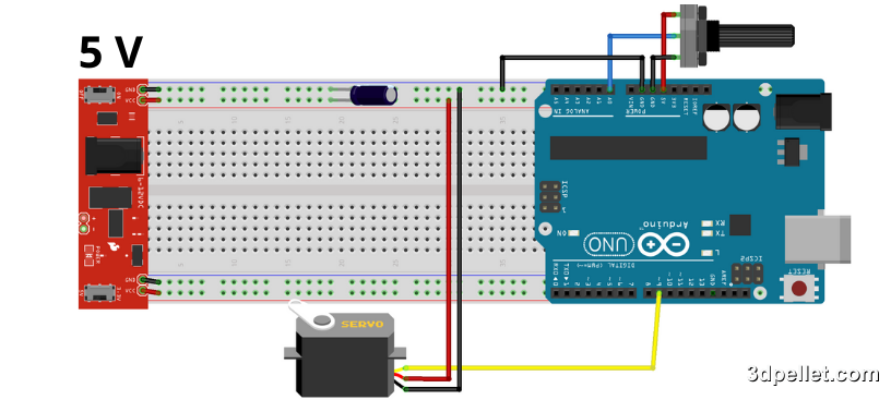
Connect the signal wire of the servo motor to digital pin 9 on the Arduino. Next, connect the Vcc and GND wires of the servo motor to the external power source. Make sure to connect the ground of the external power source to one of the GND pins on the Arduino. Add a capacitor of at least 100 μF to the input of the external power source. Connect the middle pin of the potentiometer to analog pin 0 on the Arduino and the outer pins to Vcc and GND on the Arduino.
Make sure to connect the electrolytic capacitor with the correct polarity, as otherwise it will be destroyed in a matter of seconds. The destruction of a capacitor generates heat and smoke and can even lead to a small explosion due to the compression of gases in the metal casing.
Below is a diagram of the described connection.
Note that if you wish to control the servo in a different way, you simply need to change the interface used or remove it altogether to make the servo’s movement fully autonomous. If you want to add more servos, just use additional PWM pins on the Arduino and connect their power inputs to the external power source. This power source must be capable of providing enough current to power all the servos.
When using multiple power sources, it is essential to always connect all the GND (ground) terminals. Otherwise, you risk damaging components due to potential differences between the ground references.
Arduino Code
To control the servo motor, you will use the Servo.h library, which comes pre-installed with the Arduino IDE. This basic code will make the servo motor rotate to a specified position based on the rotation of the potentiometer connected to analog pin 0.
 1// Arduino example to control a servo motor
 2// For more information: https://www.3dpellet.com
 3
 4// Include the Servo library
 5#include <Servo.h>
 6
 7// Analog pin used to connect the potentiometer
 8#define potPin 0
 9// Digital pin used to control the servo
10#define servoPin 9
11
12// Create a Servo object to control a servo
13Servo myservo;
14
15// Variable to store the value read from the analog pin
16int val;
17
18void setup() {
19  // Attach the servo to pin 9 on the Servo object
20  myservo.attach(servoPin);
21}
22
23void loop() {
24  // Read the value from the potentiometer (value between 0 and 1023)
25  val = analogRead(potPin);
26  // Scale the value to use with the servo (value between 0 and 180)
27  val = map(val, 0, 1023, 0, 180);
28  // Set the servo position according to the scaled value
29  myservo.write(val);
30  // Wait for the servo to reach the position using a software delay
31  delay(15);
32}
Additional Considerations
-
Power Supply: If your servo motor requires more current than the Arduino can provide, use an external power supply. Connect the GND of the Arduino and the external power supply to ensure a common ground reference.
-
Calibration: Some servos may require initial calibration to ensure accurate movement. Refer to the specific documentation for your servo motor for detailed calibration instructions.
Conclusion
Controlling a servo motor with Arduino is a straightforward and enjoyable task that can serve as a foundation for more complex projects, such as robots, automated mechanisms, and motion control systems. This tutorial has shown you how to make the basic connections and write the code necessary to move the servo motor to various positions. Experiment with different angles and speeds to explore the full potential of your servo motor.