How to Use a Solid State Relay with Arduino
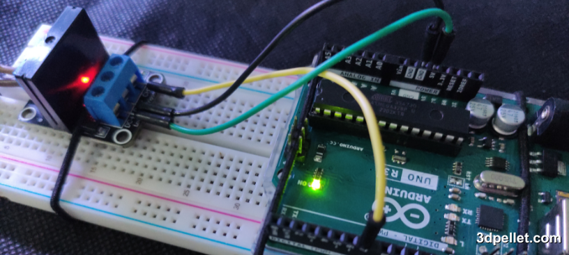
A Solid State Relay or SSR is a switching device that, unlike mechanical relays, has no moving parts. It uses electronic components to activate or deactivate circuits, making it faster, more durable, and quieter. Essentially, like mechanical relays, it acts as an electronically controlled switch. It is an actuator and can also be considered an interface between the control circuit (such as an Arduino) and the load you want to control.
Required Hardware
To follow this tutorial, you will need the following components:
- Arduino board.
- Solid-state relay module.
- Device to control (such as a lamp or a motor).
- Connection wires.
How Do Solid State Relays Work?
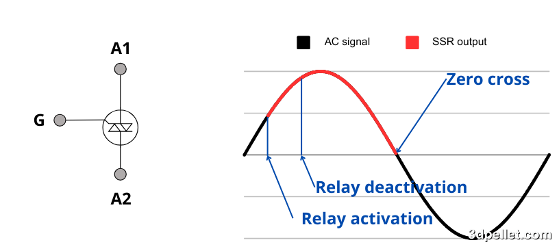
The core of an SSR designed to handle alternating current (AC) loads is a TRIAC (Triode for Alternating Current), a semiconductor device belonging to the thyristor family. Unlike a conventional thyristor, which is unidirectional, the TRIAC is bidirectional, allowing it to control current flow in both directions. Simplified, the TRIAC acts as an electronic switch capable of controlling the passage of alternating current.
TRIACs have three main terminals that are essential for their operation. These are A1 and A2, known as the main terminals, which connect to the load, and G, the control terminal. When a signal is applied to the Gate (G), the TRIAC is activated, allowing current to flow between A1 (also called MT1) and A2 (also called MT2). Once activated, the TRIAC remains conducting as long as the current through A1 and A2 stays above a minimum level called the holding current, even if the signal to the Gate is removed.
For direct current (DC) loads, SSRs use one or more MOSFETs connected in parallel to handle higher currents. This type of relay is designed to keep the control circuit input electrically isolated from the output using isolation techniques. Additionally, the positive and negative terminals are usually clearly marked, as an incorrect polarity connection can damage them.
When controlling inductive loads, such as motors or solenoids, it is essential to include a protection diode at the SSR output. This diode helps dissipate reverse currents generated when disconnecting the load, protecting the relay from potential damage.
Most SSRs incorporate an optical coupling system to ensure isolation between the control circuit and the load. The control voltage powers an internal LED, which in turn activates a photodiode or photosensitive sensor. The current generated by this component drives a TRIAC, SCR, or MOSFET, allowing the load to switch without any direct electrical connection between the two circuits.
Advantages and Disadvantages of SSR vs. Mechanical Relays
Relays, both mechanical and solid-state (SSR), are key components in electrical control systems as they allow handling of loads safely and efficiently using low voltage signals. Although both serve similar functions, their characteristics and modes of operation are significantly different, making them more suitable for certain applications. Below are the advantages and disadvantages of each type of relay, helping to determine the best option based on the specific needs of the project.
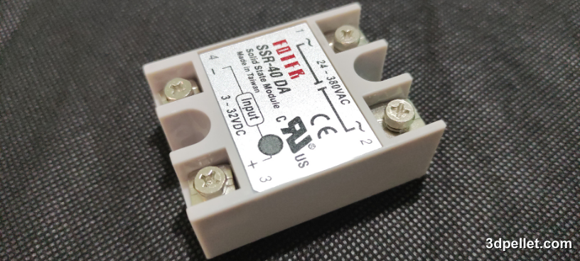
Advantages of the SSR (Solid State Relay):
-
Greater Durability: SSRs have no moving parts, eliminating mechanical wear and giving them a significantly longer lifespan than mechanical relays. This makes them ideal for applications with frequent switching.
-
Silent Operation: Unlike mechanical relays, which produce an audible “click” when activated, SSRs operate completely silently, making them useful in environments where noise must be minimized.
-
Switching Speed: SSRs are much faster than mechanical relays, with response times in microseconds. This is crucial in applications requiring rapid changes, such as temperature control systems or motors.
-
No Sparks or Electric Arcs: SSRs do not generate sparks when switching, making them safer, especially in environments where flammable gases or adverse conditions may exist.
-
Electrical Isolation: Due to the use of optocouplers, SSRs provide complete isolation between the control circuit and the load, reducing the risk of interference or damage to the control circuit.
Disadvantages of SSR vs. Mechanical Relays:
-
Higher Initial Cost: SSRs are generally more expensive than mechanical relays with similar characteristics, which may be a limitation in low-budget projects.
-
Generated Heat: Due to losses in the semiconductors, SSRs tend to generate more heat compared to mechanical relays. This may require the use of heat sinks, especially in high-current applications.
-
Leakage Current: Even when in the “off” state, SSRs can allow small currents to pass (leakage current), which can be problematic in applications where a complete shutdown is required.
-
Higher Sensitivity to Voltage Spikes: SSRs may be more vulnerable to damage from voltage spikes or electrical transients, often requiring additional protection circuits.
-
Internal Losses: SSRs have higher internal resistance compared to the metal contacts of mechanical relays, which can cause a small voltage drop and efficiency loss in high-power applications.
Choosing between an SSR and a mechanical relay depends on the specific needs of the project. SSRs are ideal for applications requiring high switching frequency, silent operation, durability, or additional safety in environments with explosion risks or flammable materials. On the other hand, mechanical relays are better suited for low-cost applications where heat dissipation and efficiency are critical, or when switching is less frequent.
SSR Connections with Arduino
SSR modules typically have the following pins:
-
DC+: Power supply for the module (usually 5V).
-
DC-: Ground.
-
CH: Control pin where the signal from the Arduino is sent to activate or deactivate the relay.
-
COM: Common terminal of the relay switch.
-
NO: Normally open connection that will close when the relay is activated.
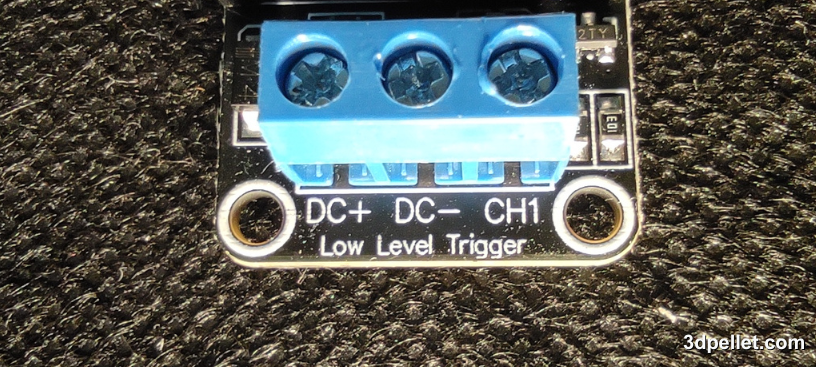
The load is connected to the COM and NO pins, which are usually labeled as SW1. The number refers to the relay number on the module, as these modules can have multiple relays on a single board. The same applies to the CH pin, which is often accompanied by a number indicating which SSR is activated by that pin.
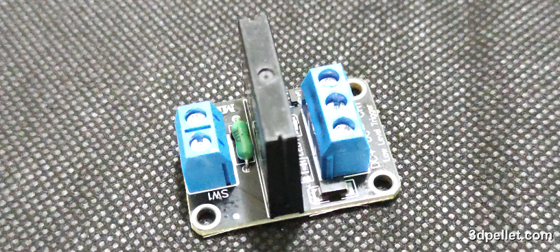
The wiring diagram for a relay is quite simple. First, you need to connect the load to the corresponding terminal of the module. It is important to note that the relay acts as a switch for the load. In most cases, it is sufficient to insert the relay into one of the poles of the load circuit to control its on and off switching.
On the other hand, the electronic part of the module needs to be powered. This is done by connecting the terminals labeled DC+ and DC- to the 5V and GND pins of the Arduino, respectively. Then, the CH1 signal pin is connected to one of the digital outputs of the Arduino. If the module has more than one channel, each additional signal pin (CH2, CH3, etc.) is simply connected to other digital outputs of the Arduino, as mentioned above.
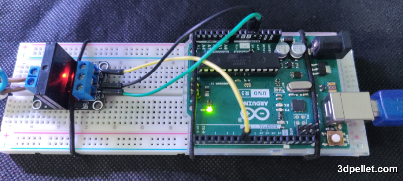
Verify that the relay is capable of handling the maximum current that the device you are going to control will consume. Common relays typically handle up to 10A at 250V AC, but it’s always better to double-check the specifications to ensure compatibility.
Example Code for Arduino
The following code shows how to control a relay with Arduino. In this example, the relay is activated and deactivated every second, turning the connected device on and off. This code is exactly the same as for the mechanical relay case, demonstrating the similarity between both devices.
 1// Arduino Example for Using a Relay
 2// More info: https://www.3dpellet.com
 3
 4// Define relay pin
 5int relayPin = 7;
 6
 7void setup() {
 8  // Set relay pin as output
 9  pinMode(relayPin, OUTPUT);
10}
11
12void loop() {
13  // Activate the relay (turns on the device)
14  digitalWrite(relayPin, HIGH);
15  delay(1000); // Wait 1 second
16
17  // Deactivate the relay (turns off the device)
18  digitalWrite(relayPin, LOW);
19  delay(1000); // Wait 1 second
20}
Conclusion:
The choice between an SSR and a mechanical relay depends on the specific needs of the project. SSRs are ideal for applications that require high switching frequency, silence, and durability, while mechanical relays are more suitable for low-cost applications or where heat dissipation and efficiency are critical.