Analog joystick with Arduino
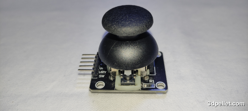
An analog joystick is an input device commonly used in control applications. They allow for detecting the movement of the lever through an analog signal from two potentiometers oriented perpendicularly. Additionally, this module commonly found in Arduino development kits includes a button or switch that is activated by pressing the lever.
In this article, I will guide you on using a 2-axis potentiometer joystick with Arduino. After understanding the operating principle, we will develop a simple Arduino and joystick project.
How does the KY-023 joystick work?
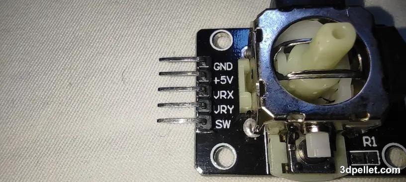
The KY-023 joystick board has five pins.
-
The GND pin is the negative power input of the board. It should be connected to GND.
-
The +5V pin is the positive power input of the board. It should be connected to +5V.
-
The VRX pin is the analog output of the X-axis and varies between 0 and 5V depending on the position of the joystick’s X-axis.
-
The VRY pin is the analog output of the Y-axis and, similar to the X-axis, varies between 0 and 5V depending on the position of the joystick’s Y-axis.
-
The SW pin is the digital output of the joystick’s button. When pressed, its level is low.
So, when you move the joystick to the left or right, the voltage at pin VRX varies within a range of 0 to 5 volts (0 representing the fully left position and 5 volts representing the fully right position). This voltage is proportional to the joystick’s position. Therefore, the reading value at the Arduino’s analog pin ranges between 0 and 1023, reflecting the joystick’s position on that specific axis. The same happens in the case of movement on the Y-axis. Regarding the button, which is active low, it’s important to note that for its use with Arduino, a pull-up resistor must be placed at the digital pin input. A simple way to do this is by enabling Arduino’s internal pull-up resistors. To do so, in the input pin configuration, we should use INPUT_PULLUP instead of the typical INPUT.
Never forget to connect a pull-up resistor to the joystick button either by connecting it yourself or by enabling Arduino’s internal pull-up resistors through software.
Example of Reading Joystick with Arduino
Now that we have seen the main components of this interface, we can connect it to the Arduino as shown in the following image.
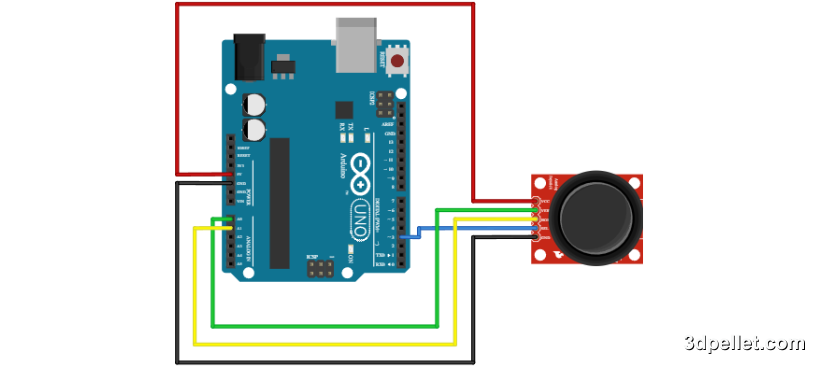
As we can see, no pull-up resistor has been connected to the button pin. Therefore, we need to enable Arduino’s internal pull-up resistors using the digital pin configuration INPUT_PULLUP. In the following code, you can see how we make this configuration. What this small program does is read the values from analog inputs A0 and A1 and print them on the serial monitor of the Arduino IDE. Additionally, it prints whether the button is pressed or released.
 1// Arduino example to use a potentiometer
 2// More information: https://www.3dpellet.com
 3
 4// We define the analog inputs and
 5// the digital input for the button
 6#define xAxis A0
 7#define yAxis A1
 8#define Button 3
 9
10void setup() {
11  Serial.begin(9600);
12  // The button will be an input with the
13  // pull-up resistor activated
14  pinMode(Button, INPUT_PULLUP);
15}
16
17void loop() {
18  // Analog pins are read
19  int xReading = analogRead(xAxis);
20  int yReading = analogRead(yAxis);
21
22  // The read values are printed
23  Serial.print("\nX Value: ");
24  Serial.print(xReading);
25  Serial.print("\nY Value: ");
26  Serial.print(yReading);
27
28  // The button state is printed
29  if (digitalRead(Button) == HIGH) {
30    Serial.print("\nButton released");
31  }
32  else{
33    Serial.print("\nButton pressed");
34  }
35
36  delay(100);
37}
Stepper motor control with A4988 and joystick
Controlling a stepper motor with the A4988 controller and Arduino is very simple and only requires two digital pins of Arduino for this task. If we also want to manually control the motor using one of the axes of our joystick, we can use the following circuit model.
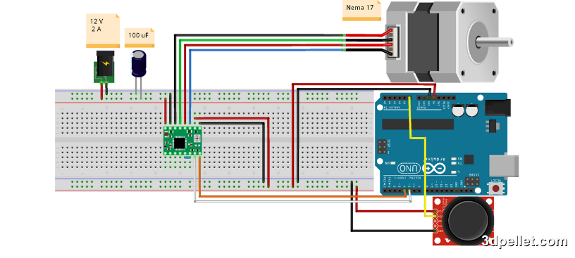
As we can see, the connection remains very simple and since we don’t need the button, we don’t need to configure the pull-up resistor. The most complex point in this example is configuring the A4988 to limit the maximum current of the motor to prevent damage. In addition to this, the only new thing here is powering the joystick and using pin A0 to read voltage values on the joystick potentiometer. The following code demonstrates how to handle this system with Arduino.
If you’re not familiar with configuring the A4988 to control a stepper motor, I suggest you learn how to do it before trying this example. Failing to limit the current passing through the motor coils can permanently damage it.
 1// Arduino example to use a potentiometer
 2// More information: https://www.3dpellet.com
 3
 4// We define the analog input,
 5// pin 4 for direction, and pin 5 for step:
 6#define xAxis A0
 7#define dirPin 4
 8#define stepPin 5
 9// With these variables, we can configure the motor speed
10#define tA 4 //4 us
11#define tB 5 //5 ms
12
13void setup() {
14  // We declare the pins as outputs:
15  pinMode(stepPin, OUTPUT);
16  pinMode(dirPin, OUTPUT);
17}
18
19void loop() {
20  // The analog pin is read
21  int xReading = analogRead(xAxis);
22
23  if (xReading > 1000) {
24    // We set the direction input to a high level
25    // for clockwise rotation of the motor:
26    digitalWrite(dirPin, HIGH);
27    // We take a step with the motor
28    stepForward();
29  } else if (xReading < 200) {
30    // We rotate the motor one full turn counterclockwise
31    digitalWrite(dirPin, LOW);
32    // We take a step with the motor
33    stepForward();
34  }
35}
36
37void stepForward() {
38    // We set the step pin to a high level for
39    // an approximate time tA
40    digitalWrite(stepPin, HIGH);
41    delayMicroseconds(tA);
42    // We set the step pin to a low level for
43    // an approximate time tB
44    digitalWrite(stepPin, LOW);
45    delay(tB);
46}
If you liked the content, help us by subscribing or leaving your like on our YouTube channel.