Connecting the LCD 1602 Module with Arduino
The LCD 1602A screen is a common type of liquid crystal display that can be easily used with any microcontroller. It serves as a visual interface between the hardware and the user. It has 16 characters on each of its two lines, which gives it the name 16x2. That is, 1602 means it has 2 lines of 16 characters. It is ideal for displaying messages, data, sensor values, and more. This is why, although it is an actuator, it is usually classified as a user interface.
An LCD, or liquid crystal display, uses liquid crystals to show characters. These crystals become opaque when an electric current is applied, blocking the backlight behind the screen. This makes that area darker compared to the rest of the display. By controlling the opacity of the liquid crystals in specific pixels, characters can be formed on the screen. Color LCD systems use the same technique, with color filters used to generate red, green, and blue.
Required Hardware
- Arduino board
- LCD screen
- 10 kΩ potentiometer
- 220 Ω resistor
- Hook-up wires
- Breadboard
Functionality Description
The LCD screen module contains a controller that manages the screen operations. This controller includes two 8-bit registers: the Instruction Register (IR) and the Data Register (DR). The IR stores instruction codes, such as clearing the screen or moving the cursor, as well as address information for accessing the screen’s data RAM (DDRAM) and the character generator (CGRAM). The DR is used to temporarily store data that will be read from or written to the DDRAM or CGRAM.
Pin Distribution
To operate, this monochrome LCD screen has 16 pins as shown in the figure.
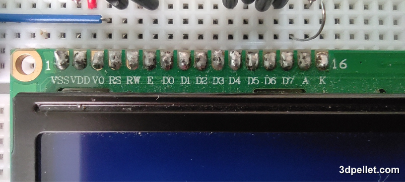
- The VSS pin is the ground.
- The VDD pin supplies power to the LCD and is typically connected to 5 volts.
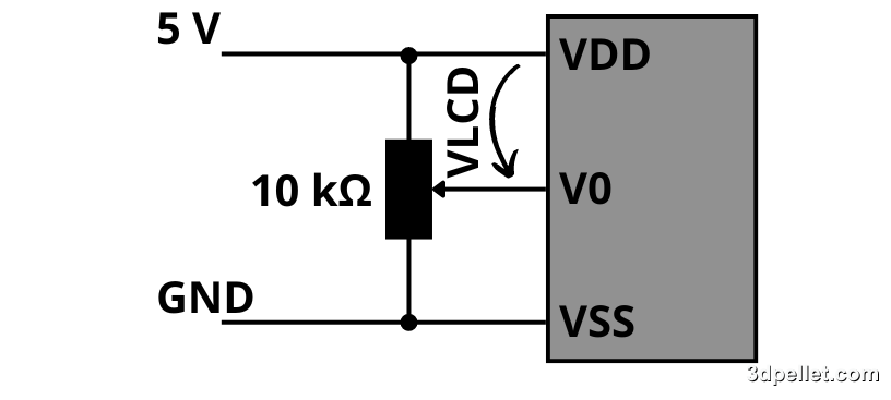
- The V0 pin adjusts the contrast of the LCD. By using a voltage divider network and a potentiometer, we can make precise contrast adjustments.
- The RS (Register Select) pin is used to distinguish between commands (such as positioning the cursor or clearing the screen) and data. The RS pin is set LOW for commands and HIGH for data.
- The RW (Read/Write) pin allows reading from or writing to the LCD. Since the LCD is usually an output device, this pin is typically kept LOW, which puts the LCD in WRITE mode.
- The E (Enable) pin activates the screen. When this pin is LOW, the LCD ignores activity on the data, RS, and RW lines; when HIGH, the LCD processes incoming data.
- The D0-D7 pins make up the 8-bit data bus that carries information to the screen. For example, to display the letter ‘A’ in uppercase, these pins are set to 0100 0001 (according to ASCII code).
- The A (Anode) and K (Cathode) pins control the backlight of the LCD.
4-bit Mode vs. 8-bit Mode
The LCD controller allows operation in two distinct modes: 4-bit and 8-bit. These modes determine how data and instructions are sent to the LCD. Below are the differences between them.
8-bit Mode:
- Uses all 8 data pins (D0 to D7) to send a full byte to the LCD in each transfer.
- Data transfer speed is higher compared to 4-bit mode.
- Programming can be simpler as data is sent in complete blocks.
4-bit Mode:
- Uses only 4 data pins (D4 to D7) to send data to the LCD, transmitting the two halves of a byte in separate operations.
- Data transfer is slower than in 8-bit mode, as it requires two transfers for each byte.
- Uses fewer data lines, which can be advantageous in systems with a limited number of input/output pins, such as an Arduino.
Although it may seem complicated, in practice it is quite simple because libraries that handle this module are often used.
Wiring Diagram with Arduino
To control the LCD with Arduino, there is not just one connection diagram, but essentially they are all similar as they require 6 digital pins, which will then be defined in the setup() function of the code. Of the 6 pins, one will be used to enable the LCD via the E pin, another for data or command selection with the RS pin, and the rest to send the bytes of information that will be written to the registers. In this example, pins D2, D3, D4, D5, D6, and D7 of the Arduino are used for this purpose. The wiring diagram for this example is as shown in the figure.
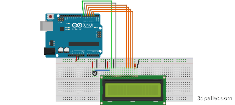
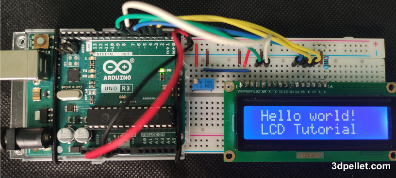
First, connect the RS pin of the LCD to digital pin 7 and the Enable (E) pin of the LCD to digital pin 6. Then, connect the D4, D5, D6, and D7 pins of the LCD to digital pins D5, D4, D3, and D2 of the Arduino, respectively. The RW pin of the LCD should be connected to ground (GND), as well as the VSS pin and K (the negative pin of the backlight LED). Next, connect the VCC pin of the LCD to 5V and the positive pin of the backlight LED (A) to 5V through a 220 Ω resistor. Finally, connect a 10 kΩ potentiometer to adjust the brightness using the V0 pin. The optimal V0 value varies with temperature, changes in VDD, and viewing angle. V0 may also vary from module to module and from batch to batch due to normal manufacturing variations.
Although a potentiometer is commonly used, V0 can also be controlled using a DAC (Digital-to-Analog Converter) or PWM (Pulse Width Modulation).
Finally, the connection diagram used in this example is as shown in the following image.
Directly connecting an LCD to an Arduino requires a large number of pins. It is often advisable to use an I2C bus adapter.
Example Code: “Hello World” on Arduino
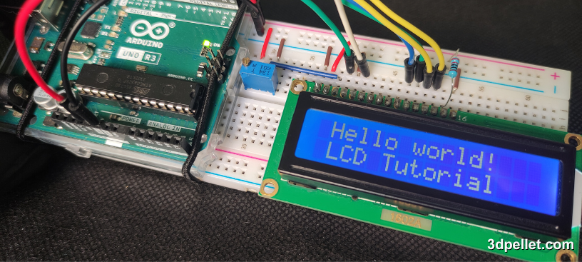
The following example code is very simple. It prints the phrase “Hello World” on the first line of the LCD screen and the phrase “LCD Tutorial” on the second line. For this, the LiquidCrystal library and the lcd.print() function are used. Additionally, the lcd.noDisplay() and lcd.display() functions are used to make the LCD screen blink. Note that in this example, the text is written to the LCD within the setup() function. This is done because the same text is displayed throughout the entire execution of the program.
 1// Arduino example for using an LCD module.
 2// More information: https://www.3dpellet.com
 3
 4// The library for controlling the LCD is included.
 5#include <LiquidCrystal.h>
 6
 7// The `lcd` object is initialized by associating the LCD
 8// interface pins with the corresponding Arduino pins to
 9// which they are connected.
10const int rs = 7, en = 6, d4 = 5, d5 = 4, d6 = 3, d7 = 2;
11LiquidCrystal lcd(rs, en, d4, d5, d6, d7);
12
13void setup()
14{
15	// A 16x2 LCD (columns, rows) is initialized.
16	lcd.begin(16, 2);
17    // Moves the cursor to the coordinates (0,0).
18	lcd.setCursor(0, 0);
19	// Writes to the LCD.
20	lcd.print("Hello world!");
21
22	// Moves the cursor to the second row.
23	lcd.setCursor(0, 1);
24	// Writes to the LCD.
25	lcd.print("LCD Tutorial");
26}
27
28void loop()
29{
30  // Turns off the screen.
31  lcd.noDisplay();
32  delay(500);
33  // Turns on the screen.
34  lcd.display();
35  delay(500);
36}
Explanation:
#include <LiquidCrystal.h>: Includes the LiquidCrystal library, which provides functions to control the LCD.LiquidCrystal lcd(rs, en, d4, d5, d6, d7);: Initializes the LCD object with the specified pin numbers.lcd.begin(16, 2);: Sets up the LCD with 16 columns and 2 rows.lcd.print("Hello World");: Prints “Hello World” on the first line of the LCD.lcd.setCursor(0, 1);: Moves the cursor to the start of the second line.lcd.print("LCD Tutorial");: Prints “LCD Tutorial” on the second line of the LCD.lcd.noDisplay();: Turns off the display.lcd.display();: Turns the display back on.delay(500);: Waits for 500 milliseconds.
This example code makes the LCD screen blink by turning it on and off every half second.
Some Useful Functions of the LiquidCrystal Library
The LiquidCrystal library offers several useful functions for controlling the LCD. Here are some of them:
lcd.home(): Places the cursor at the top-left corner of the LCD without clearing the screen’s content.lcd.blink(): Displays a blinking 5×8 pixel block at the position where the next character will be written.lcd.noBlink(): Disables the blinking of the cursor on the LCD.lcd.cursor(): Shows an underline at the position where the next character will be written.lcd.noCursor(): Hides the cursor on the LCD.lcd.scrollDisplayRight(): Scrolls the content of the LCD one space to the right. For continuous scrolling, this function should be used within a loop.lcd.scrollDisplayLeft(): Moves the content of the LCD one space to the left. Similar to lcd.scrollDisplayRight(), it should be used in a loop for continuous scrolling.lcd.noDisplay(): Turns off the LCD screen without clearing the text displayed on it.lcd.display(): Turns the LCD screen back on after being turned off with noDisplay(), restoring the text and cursor that were visible.