How to Use a Relay with Arduino
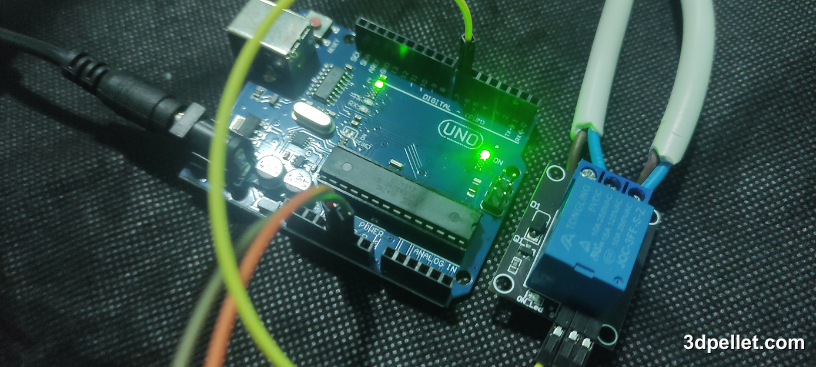
A relay is an electromechanical component that allows control of high-power or high-voltage circuits through low-power signals, like those from a microcontroller. Essentially, the relay acts as an electronically controlled switch.
Required Hardware
For this tutorial, you’ll need the following components:
- Arduino board
- Relay module (it’s recommended to use a relay module instead of a standalone relay, as these modules include components to protect your Arduino and safely manage current switching).
- Device to control (such as a lamp or a motor).
What is a Relay and How Does it Work?
When current flows through the relay’s coil, a magnetic field is generated. This field moves a switch inside the relay, closing or opening the high-power circuit. Depending on the relay type, it can be normally open (NO) or normally closed (NC):
-
Normally Open (NO): The high-power circuit is disconnected when there’s no current in the coil. It only closes when the relay is activated.
-
Normally Closed (NC): The high-power circuit is connected when there’s no current in the coil and opens when the relay is activated.
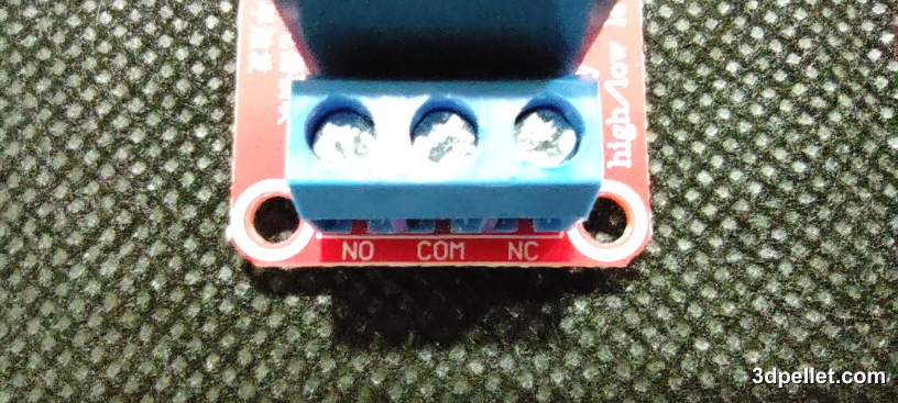
In summary, a relay allows control of a high-power device’s power state using a low voltage signal from the control circuit. A relay is an electromechanical switch that works via an electromagnet. It consists of two main parts:
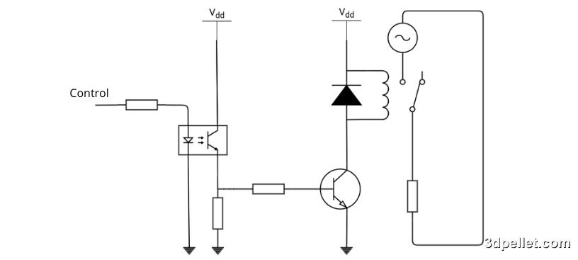
- Control Circuit (Low Power): This circuit activates the electromagnet when current is applied. It’s connected to the control signal (for example, from an Arduino).
- Switching Circuit (High Power): This circuit is activated or deactivated based on the electromagnet’s state. It’s where you connect the device you want to control, such as a lamp, motor, or other high-power device.
Relay modules usually have two control stages. Since relays are electromechanical and can wear out, an optocoupler is typically included at the module’s input to isolate the control circuit from the relay circuit. This helps avoid damage if there’s an issue with the relay. Then, an amplification stage is added to activate the relay’s inductor based on the control input.
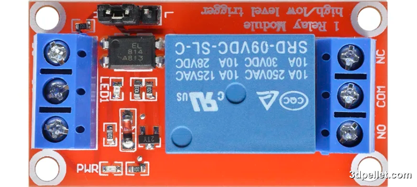
Some relay modules may not include the optocoupler. Ideally, the module should include this component. The following image shows a relay module with an EL814 optocoupler.
Types of Relays
The most common relay types in Arduino projects are electromechanical relays and solid-state relays (SSR). In this article, we’ll focus on electromechanical relays.
Relay Connections with Arduino
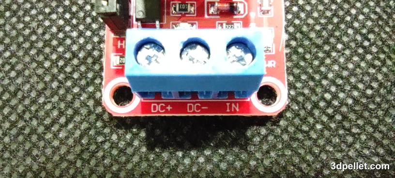
Relay modules typically have the following pins:
- DC+: Power for the module (usually 5V).
- DC-: Ground.
- IN: Control pin to send the signal from Arduino to activate or deactivate the relay.
- COM: Common terminal of the relay’s switch.
- NO: Normally open connection that closes when the relay is activated.
- NC: Normally closed connection that opens when the relay is activated.
To connect the relay module to an Arduino Uno to control an AC device, simply connect the module’s DC+ to the Arduino’s 5V pin, the DC- pin to the Arduino’s GND, and the module’s IN or S pin to an Arduino digital pin. In this example, digital pin 7 is used to control the relay.
Additionally, you need to connect the AC power supply (such as the mains) to the COM terminal of the relay and connect one of the terminals of the device you want to control (like a lamp) to the NO or NC terminal of the relay, depending on whether you want the device to connect or disconnect when the control signal is sent from the microcontroller. The other terminal of the device is connected directly to the AC power supply. This way, the relay acts as a button or switch when activated from the control terminal with the Arduino.
Example Code for Arduino
The following code shows how to control a relay with Arduino. In this example, the relay turns on and off every second, toggling the connected device.
 1// Arduino Example for Using a Relay
 2// More info: https://www.3dpellet.com
 3
 4// Define relay pin
 5int relayPin = 7;
 6
 7void setup() {
 8  // Set relay pin as output
 9  pinMode(relayPin, OUTPUT);
10}
11
12void loop() {
13  // Activate the relay (turns on the device)
14  digitalWrite(relayPin, HIGH);
15  delay(1000); // Wait 1 second
16
17  // Deactivate the relay (turns off the device)
18  digitalWrite(relayPin, LOW);
19  delay(1000); // Wait 1 second
20}
Safety Considerations
Isolation: Ensure that the control circuit (Arduino) is well isolated from the high-power circuit. Many relay modules include an optocoupler for this purpose.
Maximum Current: Verify that the relay can handle the maximum current that the device you intend to control will draw. Common relays typically handle up to 10A at 250V AC, but it’s always best to check.
Arduino Protection: Use a protection diode (flyback diode) if you are using a relay without a module to protect the Arduino from potential current spikes when the relay switches off.
Conclusion
Relays are essential components for controlling high-power devices using low-voltage signals, such as those provided by an Arduino. Thanks to their ability to act as electronically controlled switches, relays enable Arduino projects to interact with a wide range of electrical devices, greatly expanding the possibilities of what you can create.