Stepper motor with A4988 driver and Arduino
This tutorial explains how to control the movement of a stepper motor using the A4988 controller and Arduino. Wiring diagrams are included, how to set the current limit is explained, and the basic codes to control the motor from our Arduino are shown.
Required Hardware
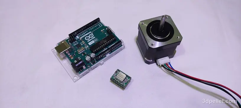
To follow this tutorial, you will need the following components:
- Arduino Uno Rev3 board.
- A4988 driver.
- NEMA 17 stepper motor.
- Connection wires.
- Breadboard.
- External power supply of 8 to 35V.
- 100 µF capacitor.
A4988 Controller Details
At the core of the A4988 is a chip made by Allegro MicroSystems known as the A4988 DMOS microstepping driver with translator and overcurrent protection. This integrated motor driver simplifies interfacing with a microcontroller (Arduino in this case), requiring only two pins to control both the speed and direction of the stepper motor.
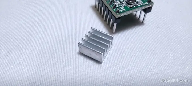
It also has five different microstep resolutions (up to 1/16th of a step). It operates from 8V to 35V and can supply up to approximately 1A per phase without heat sink or forced airflow with a rating of 2A per coil with sufficient additional cooling. The package in which this board comes usually includes an aluminum heatsink that will allow us to work with currents close to the nominal 2 A. With these characteristics, this driver is ideal for powering small or medium stepper motors, such as a NEMA 17 bipolar motor.
Minimum wiring to use this controller
To start using this controller, the manufacturer recommends using the following minimum wiring.
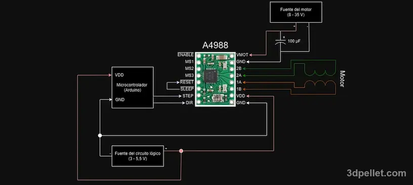
As seen in the diagram, the controller requires a supply voltage for the logic circuit (3 to 5.5V) to be connected through the VDD and GND pins and a supply voltage for the motor (8 to 35V) which connect through VMOT and GND. These supplies must have appropriate decoupling capacitors near the board and must be capable of delivering the expected currents.
This board uses low ESR (equivalent series resistance) ceramic capacitors, making it susceptible to destructive LC voltage spikes, especially when using long power cables. Under the right conditions, these spikes can exceed the maximum 35V voltage rating for the A4988 and permanently damage the board, even when the motor supply voltage is only 12V. One way to protect the controller from such spikes is to place a large electrolytic capacitor (at least 47 μF) in parallel with the motor supply.
Connecting or disconnecting a stepper motor while the controller is powered on can destroy the controller.
Be sure to connect the electrolytic capacitor with the correct polarity, otherwise it will be destroyed in a matter of seconds. The destruction of a capacitor generates heat and smoke and can even create a small explosion due to the compression of the gases in the metal envelope.
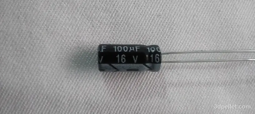
To know the correct polarity of the electrolytic capacitor, you can look at the band that indicates the negative leg.
Pins 1A, 1B, 2A and 2B correspond to the connection of the stepper motor coils. 1A and 1B correspond to the ends of coil 1 and 2A and 2B correspond to the ends of coil 2.
Step size
Stepper motors usually have a step size specification, for example 1.8° or 200 steps per revolution. A microstepping driver such as the A4988 allows for higher resolutions by allowing intermediate step locations, which are achieved by energizing the coils with intermediate current levels. For example, driving a motor in quarter-step mode will allow 200 steps per revolution motors to perform 800 microsteps per revolution by using four different current levels.
Although the minimum wiring diagram indicates that they can be left disconnected, the resolution (step size) selector inputs MS1, MS2 and MS3 allow you to select between the five step resolutions according to the following table.
| MS1 | MS2 | MS3 | Microstep resolution |
|---|---|---|---|
| Low | Low | Low | Full step |
| High | Low | Low | half step (1/2) |
| Low | High | Low | Quarter step (1/4) |
| High | High | Low | octave of step (1/8) |
| High | High | High | Sixteenth of a step (1/16) |
MS1 and MS3 have internal 100 kΩ pull-down resistors and MS1 has an internal 50 kΩ pull-down resistor, so leaving these three microstep select pins disconnected results in full step mode. For microstepping modes to work correctly, the current limit must be set low enough for current limiting to activate. Otherwise, intermediate current levels will not be maintained correctly and the motor will skip microsteps.
Control inputs
Each pulse to the STEP input corresponds to one microstep of the stepper motor in the direction selected by the DIR pin. Note that the STEP and DIR pins do not have any internal voltage, so you should not leave any of these pins unconnected in your application. If you only want rotation in a single direction, you can link DIR directly to VDD or GND.
The chip also has three different inputs to control its many power states: RESET, SLEEP and ENABLE. ENABLE is active at zero and can be left unconnected to enable the controller. In the case of the SLEEP and RESET pins, which are also active at zero, they must be connected to a high voltage to enable the controller. However, since SLEEP has a pull-up resistor connected internally, we can directly connect this pin to the RESET pin so that both have a high voltage and thus keep the controller enabled.
Maximum current limit
Before you start programming your Arduino and using the controller, you need to set the maximum current limit. This step is very important, because if you do not set a proper current limit, your motor may draw more current than it or its controller can handle and this will likely damage one or both components.
The integrated circuit manufacturer provides the following formula for calculating the maximum current.

If we want to set the maximum current we can solve the formula to know what the reference voltage should be for that maximum current. In this way we get the following expression.

The value of the maximum current is stable depending on the characteristics of our source and our motor; always respecting that this circuit can work at a maximum of 2 A. In the specifications of the motor that is being used for this tutorial it is clarified that the maximum current per phase is 1.5 A. For this reason we establish a maximum current a little more go down so as not to work at the limit.
This maximum current that we establish is the safety current and if it is exceeded, the integrated circuit automatically cuts off the power to the motor coils to prevent it from deteriorating.
With the maximum current value set, we need to know the value of the resistor RCS. If we have questions about how to find it on the board, the value can be found in the controller data sheet. Typical values for this are 0.05 Ω, 0.1 Ω or 0.2 Ω. In this case the value of RCS is 0.05 Ω.
With a maximum current of 1.4 A and a resistance of 0.05 Ω, a reference voltage of 0.56V is obtained


To set this value we must adjust the preset that appears on the board using a screwdriver, a multimeter to measure the voltage and power the logic part of the VDD and GND controller with 5 V. The following diagram shows the connection of the board with the 5V pin of the Arduino to the VDD pin of the controller and the GND pin of the Arduino to the GND pin of the controller.
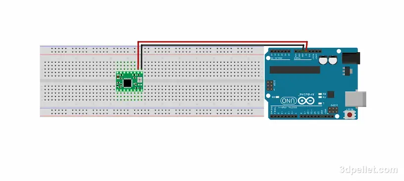
The negative of the multimeter is connected to the GND pin of the controller and the positive to the metal part of the screwdriver with which the preset is adjusted. In this way, the voltage VREF is measured and adjusted to the previously calculated value by gently turning the preset screw.
The board preset is very delicate and can be easily broken.
If your motor is making a lot of noise, try lowering the current limit. It is best to set the current limit high enough so that the motor does not lose steps.
Minimum wiring to use the controller with Arduino
After establishing the current limit, the motor source, the motor and the control pins can be connected, following the basic scheme suggested by the manufacturer as shown in the following figure.
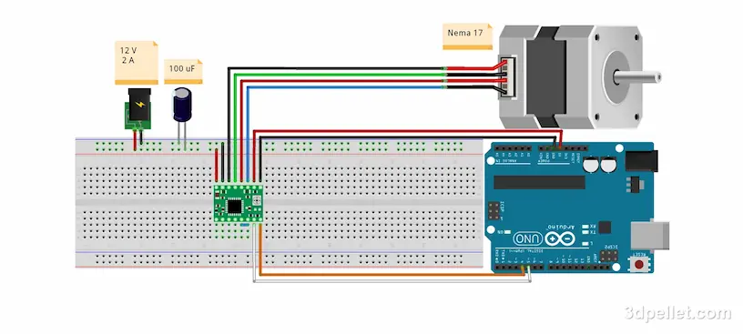
To control the speed of the motor with this configuration we can use software delays to modify the time it takes for the motor to take a step (or microstep). If we look at the timing diagram shown in the datasheet for this component, we see that the minimum duration of the step initialization pulse is 1 μs followed by a low pulse of at least 1 μs as well. It is with the sum of these two times that the total delay between motor steps is obtained. Instruction times between cycles are also added but these can in some cases be considered insignificant.
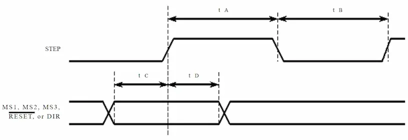
| Time duration | Symbol | Pulse size | Units |
|---|---|---|---|
| Minimum step, pulse width at High | tA | 1 | μs |
| Minimum step, pulse width at Low | tB | 1 | μs |
| Setup time | tC | 200 | ns |
| Hold time | tD | 200 | ns |
To construct the pulses, the delay functions delay(ms) or delayMicroseconds(us) can be used.
-
delay(ms) – suspends code execution for milliseconds. The delay() function causes the code to pause for the time set in the ms parameter of type unsigned long. This function allows you to pause execution from 1 ms to 50 days with a resolution of 1 millisecond.
-
delayMicroseconds(us) – Analogous to delay(), it pauses code execution for the time set in the us parameter in microseconds. The us parameter is of type unsigned int and can pause execution from 4 to 16383 μs with a resolution of 4 μs. Larger values can produce an extremely short delay. For delays longer than a few thousand microseconds, you should use delay() instead.
You should consult the maximum speed at which the motor can work in the datasheet of your motor. Many manufacturers recommend working speeds between 100 and 500 rpm. Keep in mind that the rotation speed of the motor has an inversely proportional relationship (approximately) with the torque that the motor can exert. To know the limits of your motor you must consult the torque - speed curve.
In the following code we use the delay functions to rotate the motor one full turn clockwise and counterclockwise. In this case a delay tB of 5 ms is used after an initialization pulse tA of 4 μs. The sum of these times is close to 5 ms and this is the approximate time between steps. Considering that this motor has 200 steps per revolution, at this speed, the motor completes one revolution after approximately 1 second.

 1// Arduino example to use the A4988 controller
 2// with minimal wiring.
 3// More information: https://www.3dpellet.com
 4
 5// We define the control connections, in our case
 6// pin 4 for the direction and pin 5 for the step:
 7#define dirPin 4
 8#define stepPin 5
 9// Number of steps per revolution for this motor
10#define stepsPerRevolution 200
11// With these variables we can configure the motor speed
12#define tA 4 //4 us
13#define tB 5 //5 ms
14
15void setup() {
16  // We declare the pins as outputs:
17  pinMode(stepPin, OUTPUT);
18  pinMode(dirPin, OUTPUT);
19}
20
21void loop() {
22  // We introduce a delay of one second to
23  // be able to visualize the rotation change.
24  delay(1000);
25  // We set the rotation direction input to a
26  // high level to rotate the motor clockwise.
27  digitalWrite(dirPin, HIGH);
28
29  // We rotate the engine one full turn.
30  for (int i = 0; i < stepsPerRevolution; i++) {
31    // We set the step pin to a high level for
32    // an approximate time tA.
33    digitalWrite(stepPin, HIGH);
34    delayMicroseconds(tA);
35    // We set the step pin to a low level
36    // for approximately tB.
37    digitalWrite(stepPin, LOW);
38    delay(tB);
39  }
40
41  // We introduce a delay of one second to be
42  // able to visualize the rotation change.
43  delay(1000);
44
45  // We rotate the motor one full turn counterclockwise.
46  // These lines are similar to the previous rotation.
47  digitalWrite(dirPin, LOW);
48  for (int i = 0; i < stepsPerRevolution; i++) {
49    digitalWrite(stepPin, HIGH);
50    delayMicroseconds(tA);
51    digitalWrite(stepPin, LOW);
52    delay(tB);
53  }
54}
If you liked our content, help us by subscribing or leaving your like on our YouTube channel.