I2C Communication in Arduino
I2C communication (Inter-Integrated Circuit) is a widely used synchronous serial communication protocol in electronics, especially in embedded devices and microcontrollers like those found in various Arduino boards. It was developed by Philips Semiconductor (now NXP Semiconductors) in the 1980s and is used for communication between devices. It allows multiple peripherals to connect to the microcontroller using only two pins. In this way, I2C stands out for its simplicity and efficiency.
Required Hardware
- Two Arduino boards
- Two 4.7 kΩ resistors
- Connection wires
- Breadboard
I2C Characteristics
Synchronous communication protocols are characterized by sending the clock signal along with the data signal. In this case, two lines are used for communication:
-
SDA (Serial Data Line): This is the data line that transmits information between devices.
-
SCL (Serial Clock Line): This is the clock line that synchronizes data transfer between devices.
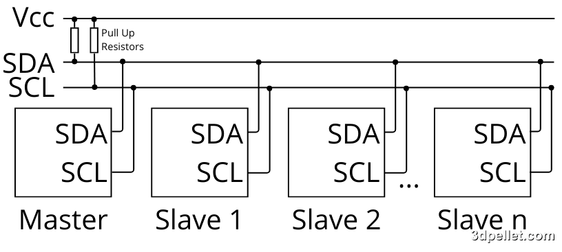
In an I2C bus, there is always a master device that controls the communication and one or more slave devices that respond to the master’s requests. Each slave device has a unique 7-bit or 10-bit address that identifies it on the I2C bus. This allows the master to communicate with a specific device. All devices are connected to the same data bus, enabling communication with multiple devices using only two pins on the board.
The address of devices can often be changed. In some cases, it can be modified via software by altering a register. In other cases, it can be changed through hardware, either via switches, jumpers, or soldering.
I2C on Arduino
Arduino includes support for I2C on most of its boards, making it easy to communicate with sensors, displays, and other devices. Arduino boards such as the Uno, Mega, and Nano use the following pins for I2C communication:
| Board | SDA | SCL | SDA1 | SCL1 | SDA2 | SCL2 |
|---|---|---|---|---|---|---|
| UNO | SDA/A4 | SCL/A5 | ||||
| Nano | A4 | A5 | ||||
| MKR | D11 | D12 | ||||
| GIGA | D20 | D21 | D102 | D101 | D9 | D8 |
| Mega & Due | D20 | D21 |
The pins labeled as SCL and SDA on the UNO R3 versions are the same as A4 and A5; they are connected on the same board for compatibility reasons with newer Shields. It doesn’t matter whether you connect to one set or the other—they are the same pins in two different positions. This means that, just like when using them for I2C, you can also use them as analog pins as long as you are not using them for I2C communication.
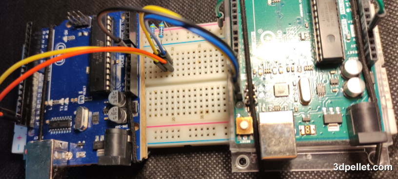
Example of Communication Between Two UNOs
Arduino provides the Wire library for working with I2C. This library allows you to configure the device as a master or slave and send/receive data easily.
Suppose we want to establish communication between two Arduino boards. One will act as the master and the other as the slave. In this example, the master will send a message to the slave, and the slave will respond to it.
The connection diagram is very simple: we only need to connect the SDA and SCL pins of each Arduino and add pull-up resistors. Additionally, we must connect the GND pins of each board to share the same reference.
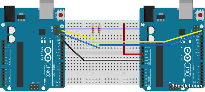
Never forget to connect the GND pins of both Arduino boards.
Code for the Master Arduino
 1// Example of Arduino using I2C bus - master
 2// More information: https://www.3dpellet.com
 3
 4#include <Wire.h>
 5
 6void setup() {
 7  Wire.begin();        // join i2c bus (address optional for master)
 8  Serial.begin(9600);  // start serial for output
 9}
10
11void loop() {
12  Wire.requestFrom(8, 6);    // request 6 bytes from peripheral device #8
13
14  while (Wire.available()) { // peripheral may send less than requested
15    char c = Wire.read(); // receive a byte as character
16    Serial.print(c);         // print the character
17  }
18
19  delay(500);
20}
Code for the Slave Arduino
 1// Example of Arduino using I2C bus - slave
 2// More information: https://www.3dpellet.com
 3
 4#include <Wire.h>
 5
 6void setup() {
 7  Wire.begin(8);                // join i2c bus with address #8
 8  Wire.onRequest(requestEvent); // register event
 9}
10
11void loop() {
12  delay(100);
13}
14
15// function that executes whenever data is requested by master
16// this function is registered as an event, see setup()
17void requestEvent() {
18  Wire.write("hello "); // respond with message of 6 bytes
19  // as expected by master
20}
Tips for Working with I2C
-
Pull-up Resistors: The SDA and SCL lines require pull-up resistors to function properly. On platforms like Arduino, it is common to omit these physical components since the Wire library automatically enables internal resistors integrated into the microcontroller. However, in external projects, it is common to use values of 4.7kΩ or 10kΩ.
-
Avoid Address Conflicts: Ensure that devices on the bus have unique I2C addresses. Refer to the device datasheet for more information.
-
Cable Length: Keep the cables as short as possible to avoid capacitance and noise issues.
The use of pull-up resistors with high values (referred to as “weak” pull-ups) causes the transitions from low to high in the signal (rising edge) to be slower. This limits the maximum communication speed and reduces the reliable operating distance between devices. To optimize performance in applications requiring higher transfer speeds or longer connections, it is recommended to incorporate external resistors with lower values, typically between 1 kΩ and 4.7 kΩ. These allow for faster signal transitions, improving communication integrity and range.
Conclusion
I2C is a powerful and straightforward interface that facilitates communication between electronic devices, especially in Arduino projects. Its implementation using the Wire library enables rapid and effective development, making this technology indispensable.