HC-SR501 Sensor with Arduino
The PIR HC-SR501 is a very popular, low-cost sensor that detects motion by measuring the infrared radiation emitted by objects in its field of view. This sensor can be used in security and automation projects. This article explains how to use this sensor with Arduino.
What is a PIR Sensor?
A PIR (Passive Infrared) sensor is an electronic device that measures infrared (IR) light emitted by objects in its field of view. PIR sensors are widely used in security systems and home automation due to their ability to detect motion. They work by detecting changes in infrared radiation levels caused by the movement of people, animals, or objects. They are composed of two fundamental parts:
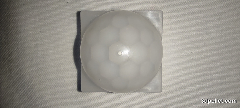
- Fresnel Lens: Amplifies the infrared radiation and focuses it on the sensor.
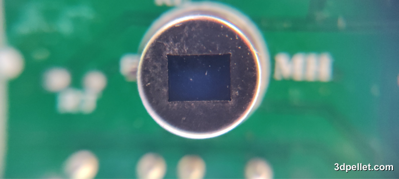
- Pyroelectric Sensor: Detects infrared radiation.
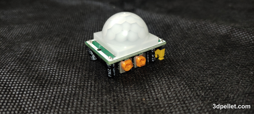
PIR Motion Sensor HC-SR501
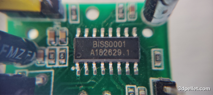
In motion sensors, the PIR sensor actually consists of 2 separate detecting elements, and the differential signal between them allows the motion alarm to be triggered. This way, when there is movement, the object passing in front of the lens causes a change in the amount of IR radiation hitting each element, generating a potential difference that translates into an electrical signal. In the case of the HC-SR501, the signal generated by the sensor enters the BISS0001 integrated circuit, which contains operational amplifiers and additional electronic interfaces. This processing circuit interprets the signal and activates the digital output.
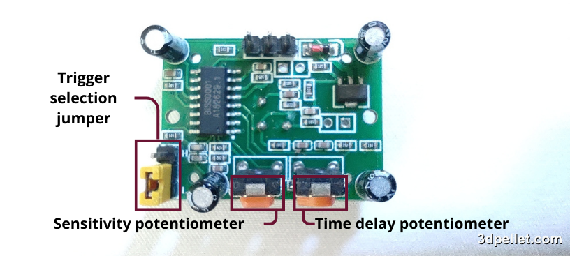
This sensor also allows for adjusting the sensitivity and detection distance using two potentiometers located on the circuit.
To configure the trigger mode, it has a jumper that allows for either a single trigger or repeated triggers.
Finally, it allows automatic light detection if a photoresistor is included.
Sensitivity Adjustment (Range)
The HC-SR501 has a maximum detection distance of 7 meters. As mentioned earlier, you can adjust the detection distance by rotating the sensitivity potentiometer clockwise or counterclockwise. By turning the potentiometer clockwise, the detection distance increases up to a maximum of 7 meters. If you turn it counterclockwise, the detection distance decreases to a minimum of 3 meters.
Delay Time Adjustment
With this potentiometer, you can adjust the time the output remains HIGH after motion detection. The minimum delay is 3 seconds and the maximum is 300 seconds or 5 minutes. Turn the potentiometer clockwise to increase the delay and counterclockwise to decrease it.
Trigger Selection Jumper
The trigger selection jumper allows you to select one of the two trigger modes. You can set it to L (single trigger) or H (repeated trigger):
- Single Trigger: The output goes HIGH as soon as motion is detected and remains so for the time set by the potentiometer. Any motion during this period is not processed and does not reset the timer.
- Repeated Trigger: Every time motion is detected, the delay timer resets.
Automatic Light Detection
This function is not available when acquiring the sensor from the factory. To activate it, a CdS (Cadmium Sulfide) photoresistor must be added, which disables the sensor’s operation if there is sufficient visible light in the area. This function is used when the sensor is required to activate only when there is low illumination.
HC-SR501 Specifications
According to the datasheet, here is a summary of the technical specifications of this sensor:
| Features | Values |
|---|---|
| Supply Voltage | 5 to 20 V |
| Detection Range | Adjustable from 3 to 7 m |
| Detection Angle | 110° cone |
| Board Dimensions | 32.5 x 24 mm |
| Mounting Holes | 2 mm |
| Fresnel Lens Dimensions | 15 mm x 23 mm diameter |
| Output Voltage Level | High 3.3 V / Low 0 V |
| Delay Time | 2.5 to 300 s |
| Lock Time | 2.5 s (default) |
| Operating Temperature | -15 to +70°C |
Connecting HC-SR501 with Arduino
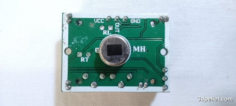
To connect an HC-SR501 PIR sensor to an Arduino board, no other components are needed. You just need to connect the GND pin to Arduino’s GND, VCC to Arduino’s 5 V, and OUT to a digital pin. In many examples, pin 2 is used. If you are unsure which pins on the sensor are which, you can temporarily remove the Fresnel lens and the pin names written on the board will be exposed, as shown in the following image.
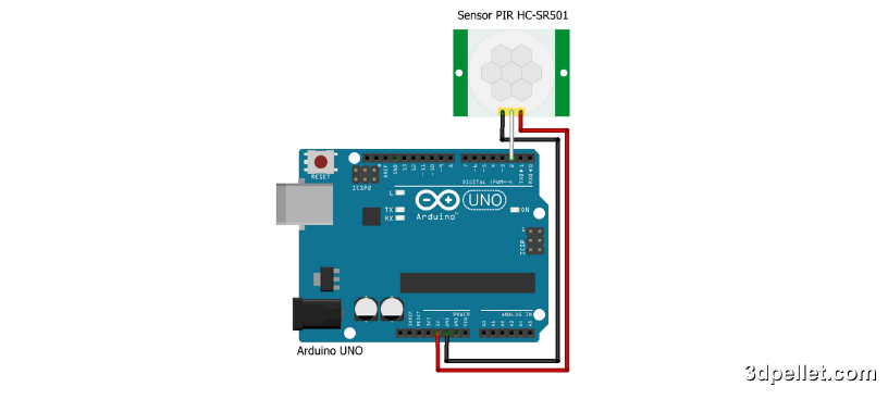
Finally, the connection is as shown below.
Code to use HC-SR501 with Arduino
The code required to perform the reading is simple. The following is a typical example of how to do it.
 1// Arduino example to use the PIR sensor HC-SR501.
 2// More information: https://www.3dpellet.com
 3
 4// We define pin 2 as the input for the PIR HC-SR501
 5#define pirPin 2
 6// We define pin 13 as the output to turn on the onboard LED
 7#define ledPin 13
 8
 9int val = 0; // Variable to store the PIR reading
10bool motionState = false; // PIR state variable
11
12void setup() {
13  // Pins are configured as input or output.
14  pinMode(ledPin, OUTPUT);
15  pinMode(pirPin, INPUT);
16
17  // Serial communication is set up at a baud rate of 9600
18  Serial.begin(9600);
19}
20
21void loop() {
22  // Read the output pin of the PIR
23  val = digitalRead(pirPin);
24
25  if (val == HIGH) {
26    // If motion is detected, turn on the LED
27    digitalWrite(ledPin, HIGH);
28
29    // Change the state and send the message
30    if (!motionState) {
31      Serial.println("Motion detected!");
32      motionState = true;
33    }
34  }
35  // If no motion is detected (pirPin = LOW), do the following:
36  else {
37    // If no motion is detected, turn off the LED
38    digitalWrite(ledPin, LOW);
39
40    // Change the state and send the message
41    if (motionState) {
42      Serial.println("Motion ended!");
43      motionState = false;
44    }
45  }
46}
Adjustments and Considerations
Sensitivity and Delay Time: As mentioned earlier, the potentiometers on the PIR sensor allow you to adjust sensitivity and delay time. Adjust these controls according to your specific needs.
Operating Environment: PIR sensors can be affected by sudden temperature changes and movements of unwanted objects. Place the sensor in a suitable location to minimize false alarms.
Use of Enclosures: Placing the sensor in an enclosure can help protect it from environmental factors and improve its performance.
Conclusion
PIR sensors are versatile and effective tools for motion detection in various applications. Connecting and programming a PIR sensor with Arduino is a relatively simple task that can be done by enthusiasts and professionals alike. With a little adjustment and calibration, these sensors can be integrated into security systems, automatic lighting, and many other innovative applications.